
Home
Tutorials Index
Tutorial - Basic Track Design
In this tutorial you will learn how to create a basic coaster track.
Difficulty: Medium
Time Required: 20 Minutes
What you need: Empty park file, created from the previous tutorial.
Step 1
Start the editor mode from the main menu by clicking on Editor
Step 2
If the park you created in the previous tutorial should still be opened, there is nothing to be done in this step. Otherwise load the park you created in the previous tutorial by selecting either Open... from the File menu, or by selecting Open Recent... which shows the list of recently opened parks.
If you do not have created the park yet, first finish the previous tutorial.
Step 3
Be sure that Top is selected from the view selection box on the top-right side of the viewport.
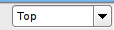
View Type Selection
Step 4
Select the Coaster tab, to open the coaster options.
Step 5
Be sure that the coaster you created in the last tutorial is selected as the current coaster. If not, please select it now using the Coaster Selection Box.
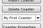
Coaster Selection Box
It is possible to have parks with multiple coasters, but only one coaster can be edited at once. The Coaster Selection Box is used to select the current coaster you want to edit.
Step 6
Before we continue we need to become familiar with the basic items a coaster track is made of. A track is made up of a series of blue balls. Each ball is called a Vertex. The correct term for multiple of those is Vertices.

Vertex
The series of Vertices will make up the Control Polygon.
Multiple Vertices forming the Control Polygon
The first vertex of a track will be displayed as a blue Socket.

Socket Vertex
The last vertex of a track will be displayed as a blue Plug.

Plug Vertex
Plugs and sockets are used to indicate that those can be connected with each other. Do worry at this moment, we will explain and use that later on.
Right now we are only interested in the control polygon which will affect the shape of the track:
Track Shape
Okay that should be enough of theory for now. Let's add some track to our coaster now...
Step 7
Select the Track tab. Among the list of track options, we will see the track related edit modes:
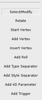
Track Edit Modes
In order to create and move vertices, we need the Select/Modify, Start Vertex, Add Vertex and Insert Vertex edit modes.
Step 8
Select Start Vertex to change to Start Vertex Edit Mode. This is used to add the first vertex to a coaster. After clicking anywhere on the viewport, a vertex should show up:
The First Vertex
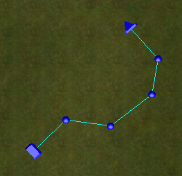
After adding the first vertex, the editor will automatically switch to Add Vertex Edit Mode. Now add a couple of more vertices by clicking on the viewport. A white line will guide you where the vertex will be appended at.
More Vertices
You can select Select/Modify to change to the Select/Modify Edit Mode. In this mode you can select and move the vertices you just created. You can select Insert Vertex to change to Insert Vertex Edit Mode. This edit mode is used to insert a vertex in between the control polygon, while Add Vertex will always add a vertex to the start or add of the control polygon.
Now try to replicate the picture above by adding and moving vertices. If you have created too many vertices, you can remove them by selecting them using Select/Modify and pressing the Delete key.
Step 9
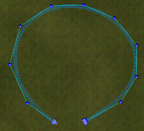
We want to make a complete circuit now. Switch to Select/Modify Edit Mode, hold down the Control Key, which is used to select multiple objects. While holding down the key, click on the Plug vertex and Socket vertex:
Plug and Socket Selected
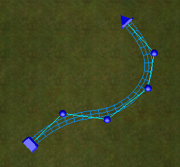
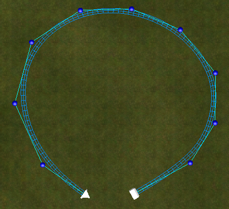
The Connect option on the Track tab should be available now. Click on it to complete the circuit:
Closed circuit
The green cone will indicate the ride direction and initial roll point. Do not worry, we will explain roll points later on. Now we want to change the height of a vertex...
Step 9
The loop of track we created is still flat. In order to change the height, we need to use different views. Now change to Perspective view by selecting Perspective on the view selection box on the top-right side of the viewport.
>> 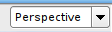
Change the View Using the View Selection Box
In Perspective view, there are two viewing modes. You can either move and edit objects (Perspective Edit Mode), or you can change the viewing position and orientation (Perspective Fly Mode).
Press the Right Mouse Button to toggle between those two modes. The mouse cursor will disappear when you are in Perspective Fly Mode. In this mode you can fly around using the W, A, S, D keys to change your viewing position. When you are done with adjusting your viewing position, switch back to normal Perspective Edit Mode using the Right Mouse Button. The mouse cursor will become visible again. In this mode, you can add and modify objects, just like in Top View.
Step 10
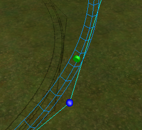
In Perspective View, move some vertices up and down. Change between Perspective Edit Mode and Perspective Fly Mode using the Right Mouse Button to adjust your viewing position and orientation. Try to replicate the following picture:
Up and Down
Step 11
Now we want to adjust the roll or banking of the track. We need to insert some Roll Points. Those are green disc objects that can be placed anywhere on a track to control the roll.
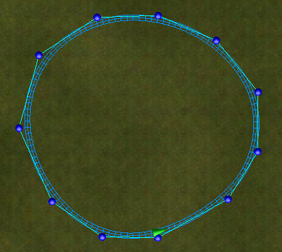
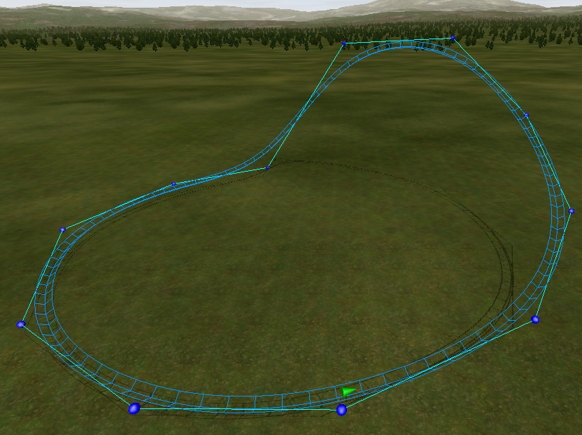
Select the Add Roll option on the Track tab to change to Add Roll Point Edit Mode. Now click anywhere on the track to add the roll point:
Roll Point
Double click on the roll point to open the Roll Point Panel. There you can change the roll angle by entering a number or by clicking on the [+] or [-] buttons.
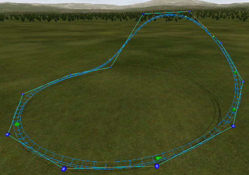
With Roll Points
In the example above, we simply added some roll points and used the default value of 0 degrees to force the track to have no roll across the full circuit.
Step 12
This tutorial ends here and you learned how to create the basic layout of a coaster track. Now save the park and we will continue to work on our coaster in the next tutorial, you will learn how to define stations, lifts and brakes.